EV charging capacitor selection starts with the power stage, not the charging station's headline output. A DC-link position, a switching snubber, and an AC filter have different duties. SMILER offers film capacitor families that can be discussed against those individual requirements. Send the converter topology, bus voltage profile, ripple information, and connection drawing to identify a candidate for evaluation. This guide describes selection considerations; it does not establish approval for a particular charger or vehicle platform.
Identify which conversion stage needs a capacitor
Texas Instruments' TIDA-010054 reference design illustrates a bidirectional dual active bridge DC/DC stage for charging stations. Its architecture distinguishes the input and output sides and supports power flow in both directions. This is useful background for explaining a charging module, not evidence that a SMILER component is used in the TI design.
Mark the intended capacitor position on your own schematic. Is the inquiry about the intermediate DC bus, a local switching position, or an AC-side filter? State whether the converter is isolated and whether reverse power flow is required. A component brief should describe the electrical conditions at that position rather than assume they equal the battery terminal conditions. Two capacitors inside the same charging module can require different voltage, current, and mechanical specifications.
Separate battery voltage from the capacitor rating
The voltage printed in a vehicle or charger specification does not by itself define every internal capacitor rating. For selection, provide the capacitor's normal operating voltage, the intended control range, and relevant excursions. Identify startup, shutdown, and direction changes where they form part of the equipment requirement. The important point is where each value applies in the circuit.
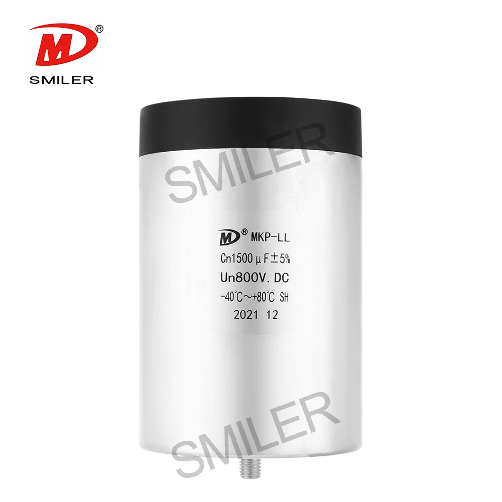
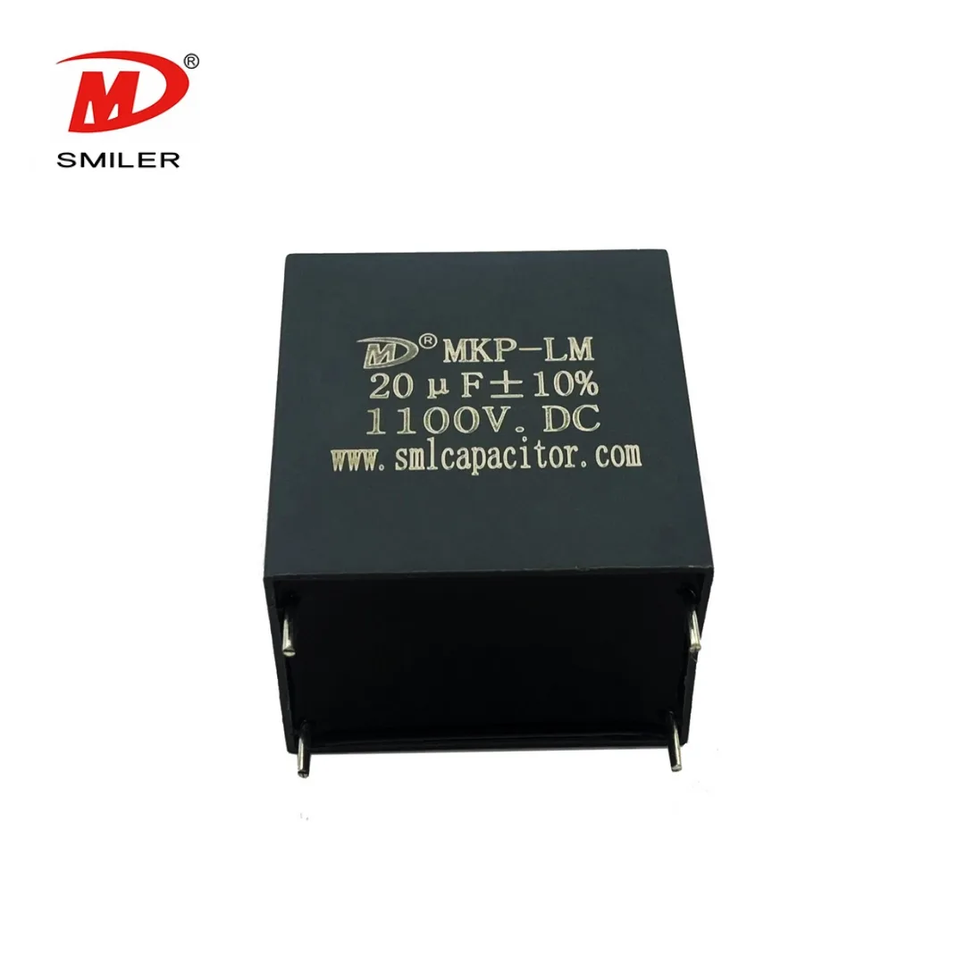
SMILER's MKP-LM family is published at 500 to 1200 VDC with 1 to 110 microfarads, while MKP-LL covers a different family range. Those ranges are starting points for an inquiry, not evidence that any endpoint combination is available or appropriate. Request one coherent proposal linking voltage, capacitance, current conditions, and package. A temporary test-voltage value should never be substituted for the part's continuous operating rating.
Give ripple duty its own line in the specification
TDK's DC-link technical overview identifies ripple current, ambient temperature, humidity protection, and packaging as separate selection dimensions. Its discussion provides a useful reminder that capacitance alone does not describe a DC-link requirement. TDK product ratings are not SMILER ratings and should not be used to fill gaps in a proposed SMILER specification.
For your charging module, supply available current waveforms or a defined ripple requirement with frequency and temperature conditions. Explain whether the data represent full load, partial load, or another operating state. If several capacitors form the intended assembly, distinguish the total requirement from the expected duty of an individual component. That allows a meaningful discussion of the proposed configuration instead of treating the charger's output current as an assumed capacitor current.

Choose the package around the power-module interface
MKP-LM is listed with a plastic case, resin filling, and two-pin or four-pin leads. MKP-LL uses an aluminum shell with a plastic bracket and resin filling, with male or female terminal options. MKP-L is described as a custom DC-link offering based on customer voltage and capacitance requirements. These differences create distinct mechanical discussion points; none makes a family automatically suitable for an EV charger.
A PCB-based design needs the lead positions, body envelope, and available height resolved. A bus-connected assembly needs the terminal geometry, mounting surface, conductor approach, and tool access considered together. If the interface is already frozen, identify which dimensions cannot move. If it remains open, compare candidate packages before the surrounding structure makes one option unnecessarily difficult to install.
Treat switching snubbers as a separate component decision
SMILER lists MKPH-S for IGBT snubbing and switch-mode power supplies, and MKPH-LS for IGBT surge absorption and high-frequency resonant circuits. Their catalog roles are different from a bulk DC-link capacitor's role. A snubber inquiry should identify the switching position, voltage transition, pulse pattern, and repetition conditions rather than borrow the main DC bus capacitance requirement.
The choice also has a mechanical aspect. MKPH-S is terminal-type with a plastic case; MKPH-LS is described with a plastic shell or Mylar tape housing and tinned copper leads. Discuss the actual connection arrangement before choosing by appearance. These are candidate families for technical review, not a claim of proven compatibility with every semiconductor technology, switching speed, or charging topology.
Assess the environment inside the charging enclosure
An outdoor charging installation does not give every internal component the same environment. For selection, describe the intended enclosure, local airflow or cooling arrangement, nearby heat sources, and any humidity requirement. Distinguish ambient temperature from a measured case temperature and from a hotspot estimate. The capacitor assessment needs the condition at its own location.
MKP-LM THB is documented with a PPS case and a defined biased humidity test. That provides a specific topic for environmental review; it is not an enclosure ingress-protection rating. Ask whether the proposed part's documented conditions address the equipment requirement. If the assembly changes during development, consider the effect on that local environment rather than assuming an earlier open-module result represents the finished charger cabinet.
Evaluate bidirectional and modular operating cases explicitly
If the equipment is bidirectional, include both power-flow requirements in the selection brief. If multiple modules share the charger load, state the operating cases the designer considers limiting. Do not assume the same capacitor duty solely because the total station output is unchanged. This is a recommendation for organizing the design assessment, not a prediction of the electrical behavior of a particular charger.
Useful comparisons identify what is fixed: the circuit topology, controller strategy, bus interface, enclosure, or component footprint. A substitute capacitor should be assessed against those constraints and the intended waveforms. A larger capacitance or a higher nominal voltage does not by itself establish an improvement. The candidate must address the actual circuit role while fitting the mechanical and thermal conditions that the module imposes.
Send a focused charging-module inquiry
Provide a circuit extract, capacitor location, voltage profile, capacitance target and tolerance, current duty, thermal conditions, and connection drawing. Add the environmental and documentation requirements that apply to the equipment. Mark estimates as estimates so unresolved design inputs remain visible. For a replacement, include the existing part specification and explain the reason for changing it.
Separate sample demand from production quantities and request current commercial terms for the proposed configuration. Platform qualification, minimum quantity, delivery timing, and warranty terms are not implied by an application page. The useful outcome of the first discussion is an identified candidate and a clear set of conditions for equipment evaluation, rather than an unsupported promise that one capacitor family covers all EV charging designs.
Frequently asked questions
Does an EV application listing mean charger approval?
No. It identifies a relevant application discussion, not qualification for a specific charger, vehicle platform, or approval standard. The proposed component needs assessment against the circuit duty, installation, environment, and documentation requirements of the equipment.
Should I choose a DC-link capacitor from station power alone?
No. Include the capacitor position and actual voltage and current requirements. Station output power does not describe the waveform at every internal component, especially when the design contains multiple conversion stages or modules.
Can a THB capacitor replace enclosure protection?
No. A biased humidity condition is a component test condition. It does not establish waterproofing or an enclosure ingress rating. Describe the environment inside the charger and assess the selected capacitor against that specific requirement.
Sources & technical reading
- www.ti.com — TIDA 010054
- product.tdk.com — index
- www.smlcapacitor.com — DC Link MKP LM
- www.smlcapacitor.com — DC Link MKP LL
- www.smlcapacitor.com — DC Link MKP L
- www.smlcapacitor.com — DC Link MKP LM THB Type
- www.smlcapacitor.com — MKPH S
- www.smlcapacitor.com — MKPH LS
External references explain general engineering principles. They do not establish SMILER product ratings or approvals.